Friday, 30 January 2015

DC 0-100V 0-50A Led Panel Volt Amp Combo Meter Digital Voltmeter Ammeter


100% Brand New.

Supply voltage: 4.5-30V (wide range)

Test voltage: 0 ~ 100V

Color of LED light: Red

Size: 4.7 x 2.8 x 1.7cm (1inch=2.54cm)

The minimum resolution below 10V: 0.01V

The minimum resolution above 10V: 0.1V

Display screen: 1.36 inch LED

Operating current:<20mA

Measuring speed:≥ 500mS / times

Accuracy: 1%(± 1 word)

Minimum operating voltage: +4.5 V

Maximum operating voltage: +30 V

Operating Humidity:1080%

Operating temperatures: -10+65

Operating pressure: 80 ~ 106kPa

Avoid direct sunlight

Note: Due to the difference between different monitors, the picture may not reflect the actual color of the item. We guarantee the style is the same as shown in the pictures. Shunt have to be purchased differently. Thank you!
.This instrument test voltage, current, power supply is taken from the test loop.No additional power supply
The the instrument test voltage supply range: DC4.5 ~ 30V,The reverse does not burn, 
Note: The maximum input voltage can not exceed 30V, otherwise there is the danger of burned 
The instrument is equipped with five wiring.Convenient access to car / battery car / motorcycle car line,,Used to monitor the battery voltage,,Grasp the battery voltage state,can also be used for other products, the use of Voltage/current measurement. 
The instrument with five lines: 
Thin black line: Header supply ground 
The Thin Red Line: Header powered regular (Note, thin red and black line between the voltage can not exceed 30V) 
Thick black lines: public test end 
Thick red line: measuring the positive voltage input terminal 
Yellow lines: current input terminal; header uses of design, the measuring end of the ground and the ground of the power supply side is the same, it is only then measured the back of the device, as shown in the following figure, the wrong will burn (such as single voltmeter, it is recommended that the yellow line with black lines together, to prevent outside interference cause ammeter digital flashing)Technical parameters: 

0.Supply voltage: 4.5 30V (wide range) 
1.Test voltage: 0 ~ 100V; minimum resolution: 0.1V 
2.Test current range: 50A resolution: 0.1A (requires an external shunt)(connect with 50A/75mV shunt) Does not include) 
3.Operating Current: <60mA 
4.Display: 0.28 "LED, two-color (red and blue) colors 
5.Dimensions: 48 × 29 × 21 mm 
6.Mounting cutout: 45.5 × 26.5 mm 
7.Measurement rate: ≥ 500mS / times 
8.Measurement accuracy: 1% (± 1 words) 
9.Extreme working conditions: 
9.1.The minimum Operating voltage: +4.5 V 
9.2.Maximum working voltage: +30 V 
9.3.Operating temperature: -10 to +65 
9.4.Operating Humidity: 10 to 80% (non-condensing) 
9.5.Working pressure: 80 ~ 106kPa 


MB102 Breadboard Power Supply Module 3.3V 5V For Arduino Solderless Breadboard


Specification:
    1.Brand new and high quality.
    2.Breadboard power supply module, compatible with 5 V, 3.3 V
    Apply to MB102 breadboard
    3.Input voltage: 6.5-12 V (DC) or USB power supply
    4.Output voltage: 3.3V/5V can switch over
    5.Maximum output current: <700 ma
    6.Fluctuation two road independent control, can switch over to 0 V, 3.3 V, 5 V
    7.On-board two groups of 3.3V, 5V DC output plug pin, convenient external lead use.
    8.Size:5.3cm x 3.5cm

    Board V1.2 A4988 Big Easy Driver 2A Phase 3D Printer Stepper Motor Driver Board


    Description: Replacement:ROB-11876. We’ve fixed a few silk screen errors on the next rev of this board including an incorrect current adjustment arrow indicator, go check it out! This page is for reference only.
    The Big Easy Driver, designed by Brian Schmalz, is a stepper motor driver board for bi-polar stepper motors up to 2A/phase. It is based on the Allegro A4988 stepper driver chip. It’s the next version of the popular Easy Driver board.
    Each BigEasyDriver can drive up to about 2A per phase of a bi-polar stepper motor. It is a chopper microstepping driver which defaults to 16 step microstepping mode. It can take a maximum motor drive voltage of around 35V, and includes on-board 5V/3.3V regulation, so only one supply is necessary. Although this board should be able to run most systems without active cooling, a heatsink is recommended for loads approaching 2A/phase. You can find the recommended heatsink in the related items below.
    Note: The arrow indicators on the current adjustment potentiometer is backwards. Keep this in mind if you’re adjusting the current limits.
    Note: This product is a collaboration with Brian Schmalz. A portion of each sales goes back to them for product support and continued development.
    Features:
    • Bi-polar Microstepping Driver
    • 2A/Phase Max
    • Max Motor Drive Voltage: 35V
    • On-board 5V/3.3V Regulation

    Tuesday, 20 January 2015

    12V Electric Solenoid Valve Magnetic DC N/C Water Air Inlet Flow Switch 1/2"

    • Material: Metal + plastic
    • Voltage:DC 12V
    • Inlet and outlet:hose barbs for 1/2" (outer  diameter) hose
    • Pressure:0.02- 0.8Mpa
    • Max fluid temperature:100°C
    • Operation mode:normally closed
    • Valve type:diaphragm (operated by Servo)
    • Usage:water and low viscosity fluids
    • Please note it is not suitable for use with  gravity fed systems
    VGA OV7670 CMOS Camera Module Lens CMOS 640X480 SCCB W/ I2C


    • Photosensitive Array: 640 x 480; IO
          Voltage: 2.5V to 3.0V;
          Operating Power: 60mW/15fpsVGAYUV;
          Sleeping Mode: <20 uA;
          Operating Temperature: -30 to 70 deg C.;
          Output Format: YUV/YCbCr4:2:2 RGB565/555/444 GRB4:2:2 Raw RGB Data (8 digit);
          Lens Size: 1/6"; Vision Angle: 25 degree;
          Max. Frame Rate: 30fps VGA;
          Sensitivity: 1.3V / (Lux-sec);
          Signal to Noise Ratio: 46 dB;
          DynamicRange: 52 dB;
          Browse Mode: By row;
          Electronic Exposure: 1 to 510 row;
          Pixel Coverage: 3.6um x 3.6um;
          Duck Current: 12 mV/s at 6'C
       
          Application:
       
          High sensitivity for low-light operation;
          Low operating voltage for embedded application;
          Standard SCCB interface compatible with I2C interface;
          Raw RGB, RGB (GRB4:2:2, RGB565/555/444),YUV(4:2:2) and; YCbCr(4:2:2)output format;
          Support VGA, CIF and from CIF to 40 x 30 format;
          Vario Pixel method for sub-sampling; Auto Image Control: AEC, AGC, AWB, ABF, ABLC;
          Image Quality Control: Color saturation, hue, gamma, sharpness and anti-blooming;
          ISP includes noise reduction and defect correction; Support image scaling; Lens shading correction;
          Flicker 50/60Hz auto detection;
          Color saturation level auto adjust;
          Edge enhancement level auto adjust;
          De-noise level auto adjust

    Monday, 12 January 2015

    StepStick Stepper motor driver A4988 3D Printer driver module Reprap Prusa


    The use chip: original A4988 chip

    Brief introduction

    A4988 is a complete microstepping motor driver with built-in translator for easy operation. The product can be full, half, 1/4, 1/8 and 1/16 step mode to operate bipolar stepper motor output drive capacity of up to 35 V and ± 2 A. A4988 includes a fixed off-time current regulator, the regulator can slow or mixed decay mode. The converter is the key to the easy implementation of the A4988. In inputting one pulse on the STEP input drives the motor one microstep. No phase sequence tables, high frequency control lines, or complex interfaces to programming. A4988 interface is very suitable for complex microprocessor is unavailable or is overburdened.

    Micro-step operation, the chopping control in the A4988 automatically selects the current decay mode (Slow or Mixed). In the mixed decay mode, the device is initially set to fast decay in the part of the fixed off-time, then a slow decay in the rest of the downtime. Mixed-decay current control scheme results in reduced audible motor noise, increased step accuracy, and reduced power consumption. Internal synchronous rectification control circuitry to improve the pulse-width modulation (PWM) power consumption when operating. Internal circuit protection includes: thermal shutdown with hysteresis, undervoltage lockout (UVLO) and crossover current protection. Special power-Sort.

    A4988 surface mount QFN package (ES), the size of 5 mm × 5 mm nominal overall package height of 0.90 mm​​, and with exposed pad for enhanced thermal dissipation. The package is Pb (suffixes-T), with 100% matte tin leadframe plating.


    Features and Benefits

    Low RDS (ON) outputs
    Automatic current decay mode detection / selection
    Mixed with slow current decay modes
    Synchronous rectification for low power dissipation
    Internal UVLO
    Crossover-current protection
    3.3 and 5 V compatible logic supply
    Thermal shutdown circuitry
    Ground Fault Circuit
    Load short-circuit protection
    Of five optional step mode: full, 1/2, 1/4, 1/8 and 1/16
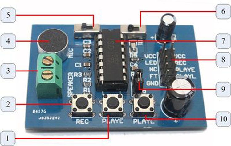
    ISD1820 voice module voice board sound recording module on-board microphone


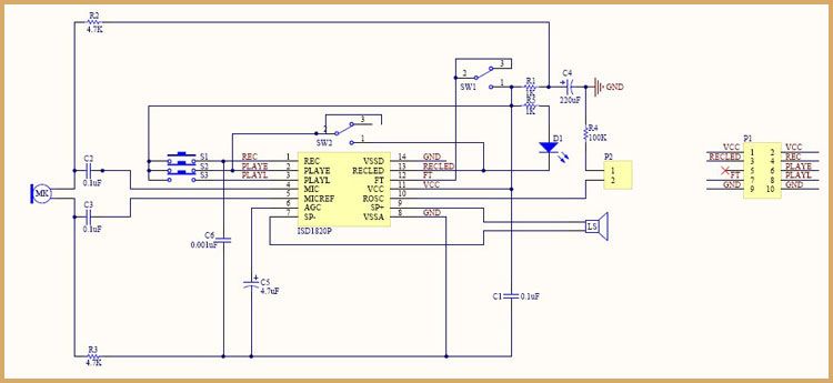
    Voice Record Module - ISD1820
    • This module is base on ISD1820, which a multiple-message record/playback device. It can offers true single-chip voice recording, no-volatile storage, and playback capability for 8 to 20 seconds. The sample is 3.2k and the total 20s for the Recorder.
    • This module use is very easy which you could direct control by push button on board or by Microcontroller such as Arduino, STM32, ChipKit etc. Frome these, you can easy control record , playback and repeat and so on.
    • Push-button interface, playback can be edge or level activated
    • Automatic power-dwon mode
    • On-chip 8Ω speaker driver
    • Signal 3V Power Supply
    • Can be controlled both manually or by MCU
    • Sample rate and duration changable by replacing a single resistor
    • Record up to 20 seconds of audio
    • Dimensions: 37 x 54 mm
    Number
    Descriptions
    1
    PLAYE - Playback, Edge-activated:When a HIGH-going transition is detected on continues until an End-of-Message (EOM) marker is encountered or the end of the memory space is reached. Upon completion of the playback cycle, the device automatically power down into standby mode Take PLAY LOW during a playback cycle will not terminate the current cycle. This pin has an internal pull-down device. Holding this pin HIGH will increase standby current consumption.
    2
    REC - The REC input is an active-HIGH record signal.The device records whenever REC is HIGH. This pin must remain HIGH for the duration of the recording. REC takes precedence over either playback(PLAYL or PLAYE) signal. If REC is pulled HIGH during a playback cycle, the playback immediately ceases and recording begins. A record cycles is completed when REC is pulled LOW. An End-of-Message(EOM) marker is internally recorded, enabling a subsequent playback cycle to terminate appropriately. The device automatically power down to standby mode when REC goes LOW. This pin has an internal pull-down device. Holding this pin HIGH will increase standby current consumption.
    3
    Speaker Outputs - The SP+ and SP- pins provide direct drive for loudspeakers with impedances as low as 8Ω. A single output may be used, but for direct-drive loud-speakers, the two opposite-polarity outputs provide an improvement in output power of up to four times over a single-ended connection will require an AC-coupling capacitor between the SP pin and the speaker. The SP+ pin and the SP- pin are internally connected through a 50KΩ resistance.When not in playback mode, they are floating.
    4
    MIC - Microphone Input, the microphone input transfers its signals to the on-chip preamplifier. An on-chip Automatic Gain Control (AGC) circuit controls the gain of the preamplifier. An external microphone should be AC coupled this pin via a series capacitor. The capacitor value, together with an internal 10KΩ resistance on this pin, determines the low-frequency cutoff for the 1800 passband.
    5
    REPLAY - loop play the record.
    6
    FT - Feed Through: This mode allows use of the speaker drivers for external signals. The signal between the MIC and MIC_REF pins will pass through the AGC, the filter and the speaker drivers to the speaker output SP+ and SP-. The input FT controls the feed through mode. TO operate this mode, the control pins REC, PLAYE and PLAYL are held LOW at Vss. The pin FT is held HIGH to Vcc. For normal operation of record, play and power down, the FT pin is held at Vss. The FT pin has a weak pull-down to Vss.
    7
    ISD1820 - IC chip
    8
    Lead Out IO - VCC LED NC FT GND / VCC REC PLAYE PLAYL GND
    9
    P2 - default short connection ROSC to 100kΩ resistance, that's means record duration is 10s
    10
    PLAYL - Playback, Level-activated, when this input pin level transits for LOW to HIGH, a playback cycle is initiated. Playback continues until PLAY is pulled LOW or an End-of-Message (EOM) marker is detected, or the end of the memory space is reached. The device automatically powers down to standby mode upon completion of the playback cycle. This pin has an internal pull-down device. Holding this pin HIGH will increase standby current consumption.
    • Voice Record Module x1


    40PCS Dupont Wire Color Connector Cable 20 CM 2.54mm 1P-1P For Arduino


    1. Product Name: Dupont wire cable 1p-1p
    2. Material:Plastic, Electronic Part
    3. Gender:  Female-to-Female (Both ends are 1-P)
    4. Length:20cm
    5. Pin pitch:2.54mm
    6. Color:Mixed colors
    7. Quantity:  40pcs/row
    6Pin PL2303HXD USB to RS232 TTLCable module for win XP win 7 8 Android OTG


    This is a newly designed product, using the Taiwan prolific production company PL2303HXD chips, PL2303HXD perfectly compatible with win XP/VISTA/7/8/8.1 / Android OTG
    The PL-2303HXD is a low cost and high performance USB-to-Serial Bridge Controller. The PL-2303HXD provides a convenient solution for connecting an RS-232 full-duplex asynchronous serial device to any Universal Serial Bus (USB) capable host. The PL-2303HXD highly compatible drivers could simulate the traditional COM port on most operating systems allowing the existing applications based on COM port to easily migrate and be made USB ready.
    Full compliance with the USB Specification v1.1
    Supports RS-232 serial interface with Programmable baud rate from 75 bps to 12 Mbps
    Supports RS422/RS485 interface
    Extensive flow control mechanism like adjustable high/low watermark level, automatic hardware or software flow control, and inbound data buffer overflow detection
    This product is designed for laboratory, product testing, low-cost MCU communications and other applications, there are four lead,
    Red +5 V
    Black GND
    White RXD
    Green TXD
    Yellow RTS
    Blue CTS
    Product Applications:
    • Single-chip upgrade solution for Legacy RS232 devices to USB interface
    • USB to RS232 converters/cables/dongles
    • Healthcare/Medical USB Interface Data Transfer Cable
    • Personal Infotainment/Media Player Docking USB Interface
    • Cellular/PDA USB Interface Data Transfer Cable
    • Serial-over-IP Wireless Solution
    • USB Barcode/Smart Card Readers
    • GPS/Navigation USB Interface
    • Point-of-Sale (POS) Terminals/Printers
    • PC Docking Station/Port Replicators
    • Industrial/Instrumentation/Automation Control USB Interface
    • USB Modem/Wireless/Zigbee USB Interface

    Sunday, 11 January 2015

    65Pcs Male to Male Solderless Flexible Breadboard Jumper Cable Wires


    65Pcs Male to Male Solderless Flexible Breadboard Jumper Cable Wires
    49 pcs 120mm length 8 pcs 150mm length 4 pcs 200mm length 4 pcs 240mm length

    Saturday, 10 January 2015

    Tutorial for ESP8266 Serial WiFi Module
    In this tutorial, we'll use a seeeduino to control the ESP8266 WiFi module to request a static page from the internet. This is a basic use of TCP socket, for other usage, please refer to the AT command guide of the module.
    Material list:
    Note: We used a software serial to print some debugging information as there’s only one hardware serial on seeeduino board. But the limitation of software serial is that it can’t communicate in a higher baud rate than 19200. So part of the output from ESP module will be dropped because the baud rate 57600 of ESP module is higher than that of the software serial. If you have a board with more than one hardware serial (e.g. Arduino Mega 2560), the case will be easier.

    Step-By-Step

    Step 1: connect module as the following picture
    Connection
    Step 2: Programe the seeeduino board.
    1. Open Arduino IDE and create a new sketch;
    2. Parse the following code into the sketch editor (need modifying the SSID and PASS macros into your own situation);
    1. #include <SoftwareSerial.h>
    2. #define SSID "xxxxxxxx"
    3. #define PASS "xxxxxxxx"
    4. #define DST_IP "220.181.111.85" //baidu.com
    5. SoftwareSerial dbgSerial(10, 11); // RX, TX
    6. void setup()
    7. {
    8. // Open serial communications and wait for port to open:
    9. Serial.begin(57600);
    10. Serial.setTimeout(5000);
    11. dbgSerial.begin(9600); //can't be faster than 19200 for softserial
    12. dbgSerial.println("ESP8266 Demo");
    13. //test if the module is ready
    14. Serial.println("AT+RST");
    15. delay(1000);
    16. if(Serial.find("ready"))
    17. {
    18. dbgSerial.println("Module is ready");
    19. }
    20. else
    21. {
    22. dbgSerial.println("Module have no response.");
    23. while(1);
    24. }
    25. delay(1000);
    26. //connect to the wifi
    27. boolean connected=false;
    28. for(int i=0;i<5;i++)
    29. {
    30. if(connectWiFi())
    31. {
    32. connected = true;
    33. break;
    34. }
    35. }
    36. if (!connected){while(1);}
    37. delay(5000);
    38. //print the ip addr
    39. /*Serial.println("AT+CIFSR");
    40. dbgSerial.println("ip address:");
    41. while (Serial.available())
    42. dbgSerial.write(Serial.read());*/
    43. //set the single connection mode
    44. Serial.println("AT+CIPMUX=0");
    45. }
    46. void loop()
    47. {
    48. String cmd = "AT+CIPSTART=\"TCP\",\"";
    49. cmd += DST_IP;
    50. cmd += "\",80";
    51. Serial.println(cmd);
    52. dbgSerial.println(cmd);
    53. if(Serial.find("Error")) return;
    54. cmd = "GET / HTTP/1.0\r\n\r\n";
    55. Serial.print("AT+CIPSEND=");
    56. Serial.println(cmd.length());
    57. if(Serial.find(">"))
    58. {
    59. dbgSerial.print(">");
    60. }else
    61. {
    62. Serial.println("AT+CIPCLOSE");
    63. dbgSerial.println("connect timeout");
    64. delay(1000);
    65. return;
    66. }
    67. Serial.print(cmd);
    68. delay(2000);
    69. //Serial.find("+IPD");
    70. while (Serial.available())
    71. {
    72. char c = Serial.read();
    73. dbgSerial.write(c);
    74. if(c=='\r') dbgSerial.print('\n');
    75. }
    76. dbgSerial.println("====");
    77. delay(1000);
    78. }
    79. boolean connectWiFi()
    80. {
    81. Serial.println("AT+CWMODE=1");
    82. String cmd="AT+CWJAP=\"";
    83. cmd+=SSID;
    84. cmd+="\",\"";
    85. cmd+=PASS;
    86. cmd+="\"";
    87. dbgSerial.println(cmd);
    88. Serial.println(cmd);
    89. delay(2000);
    90. if(Serial.find("OK"))
    91. {
    92. dbgSerial.println("OK, Connected to WiFi.");
    93. return true;
    94. }else
    95. {
    96. dbgSerial.println("Can not connect to the WiFi.");
    97. return false;
    98. }
    99. }
    Step 3: Open Serial Monitor and press the reset button of seeeduino board, you’ll see the output.
    At last, Happy Hakcing! :)