ISD1820 voice module voice board sound recording module on-board microphone
.JPG)


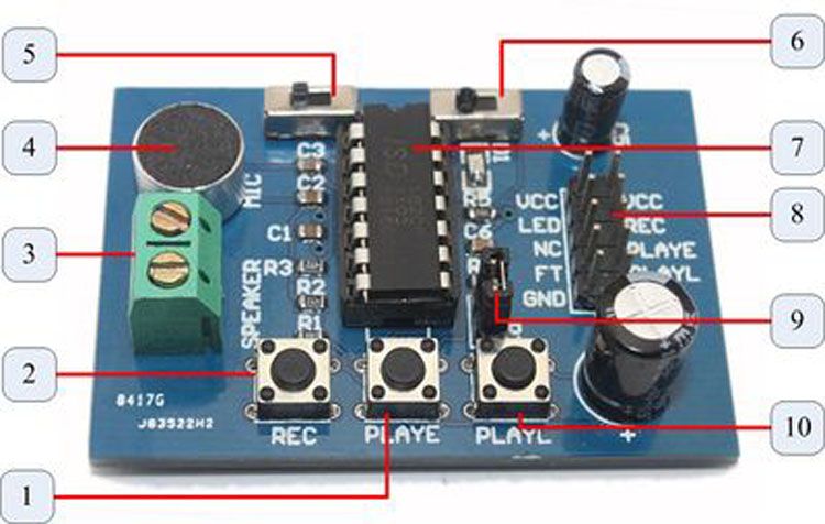
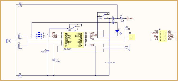
Voice Record Module - ISD1820
|
|
 |
|
 |
Number
|
Descriptions
|
1
| PLAYE - Playback, Edge-activated:When a HIGH-going transition is detected on continues until an End-of-Message (EOM) marker is encountered or the end of the memory space is reached. Upon completion of the playback cycle, the device automatically power down into standby mode Take PLAY LOW during a playback cycle will not terminate the current cycle. This pin has an internal pull-down device. Holding this pin HIGH will increase standby current consumption. |
2
| REC - The REC input is an active-HIGH record signal.The device records whenever REC is HIGH. This pin must remain HIGH for the duration of the recording. REC takes precedence over either playback(PLAYL or PLAYE) signal. If REC is pulled HIGH during a playback cycle, the playback immediately ceases and recording begins. A record cycles is completed when REC is pulled LOW. An End-of-Message(EOM) marker is internally recorded, enabling a subsequent playback cycle to terminate appropriately. The device automatically power down to standby mode when REC goes LOW. This pin has an internal pull-down device. Holding this pin HIGH will increase standby current consumption. |
3
| Speaker Outputs - The SP+ and SP- pins provide direct drive for loudspeakers with impedances as low as 8Ω. A single output may be used, but for direct-drive loud-speakers, the two opposite-polarity outputs provide an improvement in output power of up to four times over a single-ended connection will require an AC-coupling capacitor between the SP pin and the speaker. The SP+ pin and the SP- pin are internally connected through a 50KΩ resistance.When not in playback mode, they are floating. |
4
| MIC - Microphone Input, the microphone input transfers its signals to the on-chip preamplifier. An on-chip Automatic Gain Control (AGC) circuit controls the gain of the preamplifier. An external microphone should be AC coupled this pin via a series capacitor. The capacitor value, together with an internal 10KΩ resistance on this pin, determines the low-frequency cutoff for the 1800 passband. |
5
| REPLAY - loop play the record. |
6
| FT - Feed Through: This mode allows use of the speaker drivers for external signals. The signal between the MIC and MIC_REF pins will pass through the AGC, the filter and the speaker drivers to the speaker output SP+ and SP-. The input FT controls the feed through mode. TO operate this mode, the control pins REC, PLAYE and PLAYL are held LOW at Vss. The pin FT is held HIGH to Vcc. For normal operation of record, play and power down, the FT pin is held at Vss. The FT pin has a weak pull-down to Vss. |
7
| ISD1820 - IC chip |
8
| Lead Out IO - VCC LED NC FT GND / VCC REC PLAYE PLAYL GND |
9
| P2 - default short connection ROSC to 100kΩ resistance, that's means record duration is 10s |
10
| PLAYL - Playback, Level-activated, when this input pin level transits for LOW to HIGH, a playback cycle is initiated. Playback continues until PLAY is pulled LOW or an End-of-Message (EOM) marker is detected, or the end of the memory space is reached. The device automatically powers down to standby mode upon completion of the playback cycle. This pin has an internal pull-down device. Holding this pin HIGH will increase standby current consumption. |
|
 |
No comments:
Post a Comment